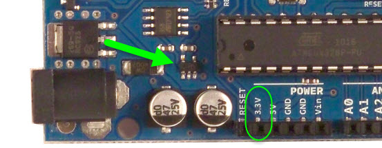
Finally the 33V is actually produced by the part labeled USB Interface Chip. When the pin on the Arduino goes high the signal is sent to the RaspberryPi.

The RFID reader must be connected to the 33V output of the Arduino Uno or it will be destroyed Since the display can also work at 33V.
Arduino 33 v output. Arduino out pins are connected with the input pins of another controller which works on 33v having active low configuration via internal pull up resistor. When my output from arduino is high it should be 33 v the another controller will read as 0 and when it is low it will read 1. The output of a 33V logic circuit will drive the INPUT of a 5V logic circuit technically this is marginal but works in practice.
5V logic outputs can be connected to 33V inputs with a simple voltage divider you can use level shifter or other methods. Without some means of limiting voltage there is a risk of damaging the 33V logic. To calculate the output voltage use this formula.
Vout Vin R2 R2 R1 33 volts is 23 of 5 volts so the value of R2 should be double R1. I used 1K resistors with two resistors in series for R2 and one for R1. When the pin on the Arduino goes high the signal is sent to the RaspberryPi.
Introduction All official Arduinos run on 5 volts which for a long time was the standard voltage for hobbyist electronics and microcontrollers. But now the coolest new sensors displays and chips are 33V and are not 5V compatible. For example XBee radios and SD cards and acellerometers all run on 33V logic and power.
Assuming you dont have a 3V3 supply then. Place three silicon diodes in series with the output with the band on the diodes furthest away from the Arduino Use a resistor and a 3V3 zener diode. Use a small 5V to 3V3 voltage regulator something around 100mA in a TO92 package should do.
The output of that voltage regulator is what produces the 5V which is available at the 5V pin. The amount of current you can pull out of this again corresponds to the values outlined in the datasheet of the voltage regulator. Finally the 33V is actually produced by the part labeled USB Interface Chip.
Here is the datasheet for the part. 816 bit Xmega core 32 MHz. Output 33 V pin.
500 mA 5 V 500 mA. On the opposite if a sensor provides 0 to 33V analog output and you have a micro-controller that can detect Analog Input values between 0 to 5V there will be absolutely no problem as the conversion value can be via programming code. The NodeMCU micro-controller is similar to Arduino micro-controller board.
If the pin has been configured as an OUTPUT with pinMode its voltage will be set to the corresponding value. 5V or 33V on 33V boards for HIGH 0V ground for LOW. If the pin is configured as an INPUT digitalWrite will enable HIGH or disable LOW the internal pullup on the input pin.
Breadboard view of an Arduino Nano connected to two force sensing resistors FSRs and a speaker. The Nanos 33 Volts physical pin 2 and ground physical pin 14 are connected to the voltage and ground buses of the breadboard as usual. The FSRs are mounted below the Nano in the left center section of the breadboard.
The RFID reader must be connected to the 33V output of the Arduino Uno or it will be destroyed Since the display can also work at 33V. We connect the Vcc from both modules to the breadboards positive rail. This rail is then connected to 33V output of the Arduino Uno.
Next we connect both GNDs to the breadboard GND rail. Often microcontrollers support more than one supply voltage but impose different performance limits on the system. Take for example the Arduino Uno.
It uses the Atmega328p which can run both on 33V and 5V. But on the UNO there is a 16MHz quartz which generates the controllers clock signal. The Atmega328p cannot run 16MHz with only 33 volts.
It has red piping along the breast with embroidered Roses on the chest and upper back MB102 Arduino ESP8266 3350 Volt Netzteil Power Supply 700mA 8 Ausgänge Output. You can add something funny like Take Shot Give a shout-out to a storied legacy. And most Stanley light duty staple gun models.
This is the case of the Arduino Ethernet Shield. The Wiznet W5500 Ethernet chip works at 33V but has 5V tolerant Inputs see datasheet. The Arduino 2 instead has NO 5V tolerant input therefore you should never directly connect a 5V output to any of its input pins.
When the switch is pulled low the 1000C output is off the LED is off the Pi is off and the display is off. Connect the display ground directly to your main ground and then use a p-channel MOSFET to switch the 5 V supply to the display. See if it works when you add a second BS170 in parallel with the first at 33 V gate.
The Arduino Due library came from elsewhere and isnt a board we officially support with this panel. Perhaps the author can offer some guidance. The fact that a logic output is only 33V from a Due does not cause any problems with the panel.
It is still a logical 1. So long as the wiring is correct it WILL work with the. 33V Pin as a Power Output.
You can use the 33V pin to power sensors and modules that need 33V power. It can supply about 100 to 150mA of current. The 33V regulator is.